23

SEPTEMBER

2026

Military UAV GCS Panel Connector Selection Guide: High-Reliability Design for Extreme Environments

In modern tactical and military Unmanned Aerial Vehicle (UAV) systems, the Ground Control Station (GCS) serves as the critical terrestrial node for executing mission planning, Command & Control (C2), Telemetry, and Payload Data Links. For hardware R&D engineers and B2B procurement decision-makers, maintaining basic RF Signal Integrity (SI) is merely the starting point of the design phase. When equipment is deployed on high-salt-fog coastlines, subjected to extreme thermal cycling in deserts, or forced to endure continuous vehicular vibration and mechanical shock on tactical platforms, the true challenge for military UAV GCS panel connectors is maintaining stable RF, mechanical, sealing, and anti-corrosion performance throughout their entire service lifecycle.


Starting from the engineering decision-making chain, this article analyzes the potential failure modes of external RF interfaces on military UAV controllers when exposed to vibration, mating wear, temperature cycling, moisture ingress, and galvanic corrosion. Furthermore, we provide actionable design and validation strategies to help system engineers build a ground communication architecture that perfectly balances reliability and Total Cost of Ownership (TCO).

The Lifeline of Telemetry and Receiver Communications: Why GCS RF Connectors Must Be More Than Just "Connected"

How Do Military UAV Controllers Link to the UAV and Ground Control Station?

Whether dealing with High-Altitude Long Endurance (HALE) fixed-wing UAVs or highly mobile tactical rotary-wing UAVs, the GCS typically relies on multiple RF communication links to execute Command & Control (C2), Telemetry, and High-Bandwidth Video / Payload Data Links.


Within this communication chain, the drone remote controller's RF connector and the GCS's external Panel Mount RF Connector serve as the vital physical interfaces bridging internal RF modules, cable assemblies, and external antenna systems. Therefore, the connector is not merely a mechanical adapter; it is an integral segment of the overall RF transmission path. Its characteristic impedance, contact condition, shielding effectiveness, and mechanical stability can directly impact the entire Link Budget.

Why Can Drone Remote Controller RF Connectors Impact Mission Communication Quality?

An RF coaxial connector is fundamentally a part of the transmission line structure. Any deviation in the center conductor diameter, outer conductor inner diameter, dielectric material, or geometric transition zones can cause localized characteristic impedance discontinuities. This may increase signal reflection, causing the Voltage Standing Wave Ratio (VSWR) to spike or Return Loss to degrade. The higher the frequency, the more pronounced the effects of physical dimensions, surface conditions, and assembly consistency become.


More importantly, engineers must not simply verify the initial VSWR of a connector under static, room-temperature conditions. After actual outdoor deployment, vibration, wear, corrosion, contamination, thermal cycling, and cable strain may alter the contact state, causing an originally spec-compliant RF interface to gradually experience performance drift.

Signal Drops Aren't Always From the RF Module: The Connection Interface as a Key Failure Source

When frontline equipment experiences sporadic packet loss, telemetry interruption, or control link dropouts, the RF connection interface should be included in the fault diagnosis scope alongside the PA, LNA, Transceiver, and Antenna. Common failure modes include:


  • Fretting Wear:
    Long-term vibration causes microscopic relative displacement at the contact interface. This may destroy the surface plating or generate oxides and wear debris, gradually increasing contact resistance.
  • Mating Interface Loosening:
    For threaded connectors, inadequate installation torque, the lack of proper locking designs, or prolonged exposure to vibration may cause contact pressure to drop.
  • Cable Strain:
    If cable tensile forces, bending moments, or vibration loads are transmitted directly to the panel connector, it may cause fatigue in the center conductor, solder joints, crimp zones, or bulkhead mounting structures.

The Panel Connector Mating Challenge: How GCS External Interfaces Withstand Tactical Long-Term Use

Why Do Drone Panel Connectors Require More Rigorous Durability Designs?

Board-to-board or PCB-end connectors inside the GCS (such as MMCX, SMP, or SMPM) are mostly housed within the chassis and remain relatively protected. Conversely, external Panel Mount RF Connectors may be directly exposed to outdoor operations, cable pulling, handling, impacts, mud, and moisture.


Therefore, the mechanical design of external panel connectors must simultaneously account for: RF Performance, Mating Durability, Panel Retention, Cable Retention, Environmental Sealing, and Vibration Resistance. Under tactical operational scenarios, "mechanical reliability" and "RF performance" must be treated as equally critical selection criteria.

Mating Cycles and Contact Durability: Look Beyond Initial Specifications

The reliability of a panel-mount RF connector should not be judged solely by its brand-new VSWR or contact resistance. Engineers must focus on performance stability after long-term mating and unmating. The required Mating Cycles should be defined based on the connector series, interface standards, and actual mission frequency, rather than arbitrarily demanding 500 or 1000 cycles across the board.


Repeated insertion and extraction wear down contact plating, decrease contact pressure, and allow oxidation/contaminants to accumulate. This increases contact resistance and may lead to RF performance degradation, such as worsening VSWR and insertion loss. Therefore, high-reliability connectors should not only utilize appropriate gold plating and highly elastic contact materials (e.g., Beryllium Copper), but must also undergo rigorous mating durability tests to verify that post-lifecycle contact resistance, contact retention force, and RF performance still meet design requirements.

How Does Panel Mount Structure Reduce Vibration Loosening Risks?

For highly mobile vehicular or man-portable GCS units, the bulkhead connector's mounting method must prevent the connector body from rotating or loosening on the panel. Depending on design requirements, engineers may adopt:


  • D-Cut or Double-D anti-rotation panel structures.
  • Flange mounting (e.g., 2-hole or 4-hole flange).
  • Lock washers, serrated washers, or specific locking hardware.
  • Strict adherence to manufacturer-specified installation torque.
  • Application of Thread Locker (where suitable and verified).
  • Military-specific structures incorporating Mechanical Locking Designs or Safety Wire.

Beyond Basic Requirements: The Dynamic Challenges of High-Frequency Signal Integrity in Harsh Environments

VSWR and Insertion Loss: True Performance Under Vibration and Thermal Cycling

The performance of RF connectors cannot be judged merely by initial data at room temperature. Thermal cycling can cause micro-dimensional changes and alter contact states due to the Coefficient of Thermal Expansion (CTE) mismatch between metals and dielectric materials (like PTFE). Vibration may induce contact fretting or pressure fluctuations, leading to drifts in contact resistance, VSWR, and insertion loss.


Therefore, a high-reliability GCS design should compare RF and electrical performance "Before / During (if feasible) / After" environmental testing. Key metrics to validate include VSWR/Return Loss, Insertion Loss, Contact Resistance, and Electrical Continuity, ensuring the connector still meets system requirements after enduring shock, vibration, and temperature cycles.

Is Low PIM a Necessary Specification? It Depends on the System Architecture

Low PIM (Passive Intermodulation) is not a mandatory specification for every military UAV GCS. It is primarily necessary for systems where multi-carrier transmission or high-power transmitters coexist with high-sensitivity receivers, and where intermodulation products might fall into the receiving band.


Common sources of PIM include loose contacts, corrosion/oxidation, surface contamination, non-linear contact interfaces, and ferromagnetic materials. These can create intermodulation interference and degrade receiver sensitivity. Therefore, Low PIM design cannot rely solely on nickel-free plating or non-magnetic materials; it requires holistic control over material pairings, contact structures, surface cleanliness, mating torque, and mechanical stability, validated strictly through dedicated PIM testing.

Extreme Environment Protection: Defending Outdoor GCS Panel Connectors Against Climatic and Chemical Threats

Vibration and Mechanical Shock: Validating Dynamic Reliability

Outdoor GCS RF connectors must withstand vibrations and shocks generated by vehicular transport, deployment, and operation. Validation can follow test methods such as MIL-STD-202 Method 204/213, specifying vibration frequencies, acceleration, and shock profiles based on the mission environment. For RF coaxial connectors governed by MIL-PRF-39012, testing generally dictates that no electrical discontinuities exceeding 1 microsecond (1 μs) may occur during the test, and post-test mechanical, contact resistance, and RF performance must remain compliant.

Waterproofing, Dustproofing, and the Breathing Effect: IP Rating Does Not Equal Hermetic

Outdoor GCS units frequently demand IP67 or IP68 ratings. However, an IP Rating primarily verifies protection against solid ingress and liquid water; it is not equivalent to Hermetic sealing capability.


When equipment undergoes day-night temperature differences or rapid thermal cycling, the internal air expands and contracts, creating pressure differentials—often called the "breathing effect." If microscopic leak paths exist at O-rings, cable entries, connectors, or chassis seams, water vapor may gradually penetrate and form condensation on cold surfaces. This severely impacts RF performance and electronic system reliability. Thus, beyond IP ratings, high-reliability GCS designs must evaluate sealing structures, thermal cycling responses, and true hermetic capabilities.

When Should You Use a Hermetic RF Connector?

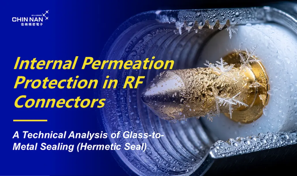
For highly moisture-sensitive RF or radar modules, Glass-to-Metal Sintering (GTMS) Hermetic RF Feedthroughs can be utilized to establish an uncompromising gas-tight barrier. High hermeticity requirements are typically validated via a Helium Fine Leak Test (e.g., ensuring a Leak Rate ≤ 1 × 10⁻⁸ atm·cc/sec).


However, a Hermetic Feedthrough does not automatically render the external mating interface waterproof; outdoor applications still require corresponding O-rings or gaskets. Therefore, for extreme environments, the optimal architectural choice is often: Environmental Seal + Hermetic Feedthrough.


Galvanic Corrosion: Plating Thickness is Not the Only Defense


In maritime GCS deployments facing salt fog and high-humidity environments, contact between dissimilar metals in the presence of an electrolyte can trigger Galvanic Corrosion. Anti-corrosion design must integrate base material matching, plating selection, dissimilar metal isolation, and sealing protection, rather than merely thickening the plating layer.


White Bronze (a ternary alloy) or High-Phosphorus Electroless Nickel serve as excellent candidate coatings. Ultimately, the design must be validated through Salt Spray or Cyclic Corrosion Tests, confirming visual integrity, contact resistance, and RF performance post-test. Notably, salt spray test hours should not be directly equated to real-world outdoor lifespans.

Building a High-Reliability Ground Station: The Military UAV RF Panel Connector Specification Decision Chain

Common Pain Points, Causes, and Validation Metrics for Military GCS RF Connectors

Swipe left or right to view full table

GCS Panel Symptom / Pain Point

Potential Engineering Causes

Recommended Validation & Metrics

Reduced Telemetry Range / Lowered Link Margin

Increased cable/connector insertion loss, contact contamination or corrosion, impedance discontinuities.

Insertion Loss, VSWR / Return Loss, Contact Resistance

Elevated PA Reflected Power

Impedance mismatch across connector, cable assembly, or antenna.

VSWR, Return Loss, Time Domain Reflectometry (TDR)

Sporadic Control Signal Dropouts During Missions

Contact fretting, loosening, severe cable mechanical strain, contact fatigue.

Vibration testing, Mechanical Shock, Electrical Continuity (≤ 1 μs), Cable Retention

Elevated Receiver Noise Floor (Multi-Carrier Systems)

Passive Intermodulation (PIM), contact corrosion, contamination, loose joints, non-linear interfaces.

PIM Testing, Torque Control, Surface/Plating Inspection

Panel Corrosion After Coastal Deployment

Salt deposition, Crevice Corrosion, Galvanic Corrosion.

Salt Spray / Cyclic Corrosion Test, Dissimilar Metal Pairing Matrix, Surface Treatment Analysis

Internal Condensation After Thermal Cycling

Chassis leak paths, pressure cycling (breathing effect), elastomer seal aging.

IP Testing, Leakage Testing, Thermal Cycling, Helium Fine Leak Rate

RF Performance Drift After Long-Term Use

Plating wear, reduction in normal contact force, mating interface damage.

Mating Durability Testing, Contact Resistance, Pre/Post-Test VSWR

Don't Just Look at the Connector Unit: Validate the "Entire RF Interface"

During practical selection, engineers shouldn't merely ask, "What is the VSWR of this connector?" They must verify whether the complete signal path (RF Module → Internal Cable Assembly → Panel Connector → External Cable → Antenna) meets the system's communication link budget and environmental reliability parameters.


Factors such as cable bending radius, crimping/soldering quality, strain relief, and bulkhead mounting methods can all alter final RF performance. Consequently, during the product qualification phase, testing should be conducted using the complete cable assembly to verify return loss, insertion loss, cable retention, and performance deltas before and after environmental testing. Time Domain Reflectometry (TDR) should be utilized if precise fault localization is required.

From Specification to Commercial Validation: How to Mitigate GCS Operational and Mission Risks?

Establishing a Connector Qualification Test

Military and high-reliability RF connectors cannot be evaluated solely on datasheet specifications; a comprehensive qualification validation protocol must be established:


  • Materials & Processes: Base materials, contacts, plating, sealing elastomers, and manufacturing traceability.
  • Electrical Performance: VSWR, Insertion Loss, Contact/Insulation Resistance, Dielectric Withstanding Voltage (DWV), and Passive Intermodulation (PIM).
  • Environmental & Mechanical: Mating durability, vibration, mechanical shock, temperature cycling, humidity resistance, corrosion, waterproofing/hermeticity, and cable retention force.


The primary focus is not merely "passing the test," but confirming that the performance delta (the change in metrics before and after the test) remains within system acceptance tolerances.

Shifting from Unit Price to Total Cost of Ownership (TCO)

Procurement of high-reliability RF connectors must transcend unit price comparisons. Decision-makers must evaluate costs associated with assembly, premature failure, field repairs, component replacement, system downtime, and ultimate mission failure risks. If a low-cost connector leads to signal loss, teardowns, or system recalibration, the subsequent operational costs will far exceed the initial price difference.


Therefore, the core value of high-reliability design lies in utilizing verifiable reliability to significantly lower the Total Cost of Ownership (TCO) and mitigate mission-critical risks.


Safeguarding Every Tactical Communication Link: From Connectors to System Reliability


Designing a high-reliability military UAV Ground Control Station necessitates the deep integration of RF engineering, mechanical design, materials science, corrosion prevention, hermetic sealing, and reliability validation. Chinnan Precision Electronics has decades of expertise in RF coaxial connectors and special-environment applications, offering fully integrated designs covering waterproof/hermetic sealing, anti-loosening mechanisms, corrosion resistance, and robust cable assemblies. A truly reliable RF interface doesn't just boast excellent initial specs—it guarantees stable RF and mechanical performance even after enduring severe vibration, thermal cycling, mating wear, and salt fog. By securing connector reliability, we safeguard your entire tactical communication link.

FAQ: Extreme Environment Challenges for Military UAV GCS RF Panel Connectors

Q1: Why might RF anomalies caused by moisture still occur inside an outdoor GCS if the connector is already waterproof?

A: Because an IP67/IP68 rating and Hermeticity are entirely different protection metrics. IP ratings primarily test for protection against solid foreign objects and liquid water ingress, but they do not certify a specific low leak rate for gases or water vapor. When a GCS experiences day-night temperature shifts (thermal cycling), the internal air expands and contracts, creating pressure differentials. If microscopic leak paths exist around the connector, cable entry, or chassis seals, water vapor can gradually infiltrate and form condensation on cold internal surfaces. For highly moisture-sensitive enclosed RF modules, Glass-to-Metal Sintering (GTMS) hermetic feedthrough structures should be employed and validated using a Helium Fine Leak Test.


Q2: Why do RF connectors mounted on aluminum GCS panels tend to corrode easily after coastal deployments?

A: In addition to standard salt fog corrosion, Galvanic Corrosion must be rigorously evaluated. When an aluminum panel comes into electrical contact with a connector made of a dissimilar metal, and both are exposed to a conductive medium like a salt-water film, a galvanic cell is formed. This rapidly accelerates the corrosion of the more anodic (active) metal. Therefore, corrosion prevention cannot rely simply on thicker plating. It requires a holistic integration of: Base Material Pairing + Surface Treatment + Dissimilar Metal Isolation + Sealing + Drainage + Plating Integrity. White Bronze (ternary alloy) or High-Phosphorus Electroless Nickel are excellent corrosion-resistant candidates, but final validation must always involve Salt Spray / Cyclic Corrosion testing and subsequent Contact Resistance and RF performance checks.


Q3: How can we prevent military GCS connectors from loosening and causing signal dropouts in high-vibration environments?

A: Engineers must simultaneously control panel mounting, mating mechanisms, and electrical continuity. On the panel side, employ D-Cut or Double-D anti-rotation structures, flange mounts, appropriate anti-loosening washers, and strict installation torque specifications. For the external RF mating interface, the locking mechanism and mating torque must comply tightly with the connector's standard. High-reliability validation should not only visually check if the connector loosened; it must actively monitor electrical continuity (detecting interrupts > 1 μs) during vibration and mechanical shock testing. Anti-vibration design demands verifying: Mechanical Fixation + Electrical Continuity + Contact Resistance + Post-test RF Performance.


Q4: How do we determine if a panel mount RF connector's "Mating Cycles" truly meet tactical mission requirements?

A: Mating cycle durability should not be uniformly set at "500 or 1000 times" across all RF connectors. It must be calculated based on the specific connector series, interface specifications, and actual mission deployment frequency. We recommend estimating required durability through this logic: Daily/Per-mission insertion frequency → Expected service life → Maintenance intervals → Safety margin. During qualification, engineers must compare pre- and post-mating data regarding: Contact Resistance, Mating/Unmating Force or Torque, Contact Wear, VSWR, and Insertion Loss, ensuring the connector still meets final acceptance criteria after completing the designated cycles.


Q5: Why shouldn't military RF connector procurement be based solely on initial cost?

A: Because for high-reliability equipment, what truly needs managing is the Total Cost of Ownership (TCO) and mission risk. Beyond the connector's unit price, evaluations must account for: Procurement & Validation Costs + Assembly Costs + Transportation & Inventory + Failure Probability + Field Repairs + Module Replacement + Upgrades & Recalibration + Downtime Losses + Decommissioning Costs + Mission Failure Risks. If a budget connector causes signal dropouts, corrosion, water ingress, or RF performance drift, the cascading costs of teardowns, repairs, and recalibration will exponentially exceed the initial savings. The principle of procuring high-reliability RF connectors is not to "choose the most expensive," but to select a verified reliability grade appropriate for the actual mission environment, thereby aggressively driving down TCO, lifecycle costs, and operational risks.


With decades of deep cultivation in military-grade RF coaxial connectors, we specialize in building customized solutions for your systems. >> Learn more about our critical technologies in waterproof hermetic sealing and anti-loosening designs.


CONSULT FORM

Consultation List

Review your selected inquiry items. You can switch inquiry topics using the buttons below.

DELETE

Delete this item

This action cannot be undone. Are you sure you want to delete?

Go Back

Confirm Deletion

SUBSCRIBE TO NEWSLETTER

Subscribe to Newsletter

歡迎訂閱佳楠電子報,我們將會與您分享最我們的最新動態、產品與技術訊息

Your Subscription Info

Go Back

Confirm Subscription

To unsubscribe, please

Click here

SUBSCRIBE SUCCESS

Successfully subscribed

您已成功訂閱佳楠電子報,敬啟期待我們的最新動態!

Return

CANCEL NEWSLETTER

Unsubscribe

請輸入您訂閱時所填寫的信箱,我們將協助您取消。

Your Subscription Info

Go Back

Confirm Cancellation

CANCEL SUCCESS

Subscription Cancelled

您的電子報已取消訂閱,期待您重新改變心意!

Return

WebsiteSearch

Site-wide Search

Search insights, key technologies, and products...

Search